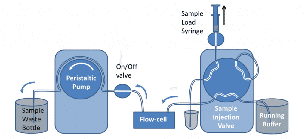
Pump Flow Control with Manual Sample Introduction
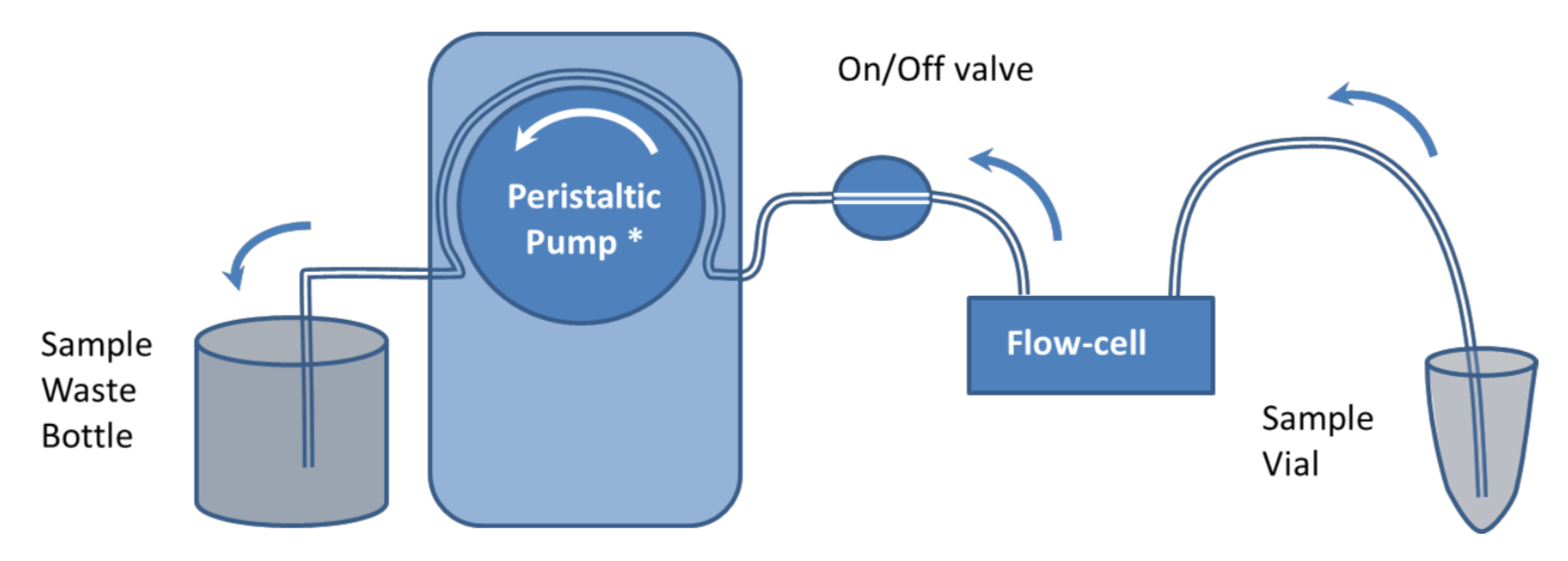
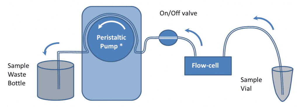
It is recommended that samples are introduced to the QCM-I flow-cells using a pump to control the flow. In the simplest setup, shown in figure 1, a peristaltic pump* is used to suck buffer directly from a beaker or other container. Sample is introduced to the flow-cell by briefly stopping the flow, transferring the end of the tube to the sample vial and restarting the flow again.
This simple setup can be used for most experiments; however the manual method of introducing a sample can impact the reproducibility and the quality of the data in the experiments. Under constant flow conditions, if the sample chamber temperature is set well above or below room temperature, changes in the flow rate can cause transient excursions in the QCM-I signal. Care should be taken to ensure no bubbles are introduced to the flow in the process. The pump can be reversed to remove them if necessary.
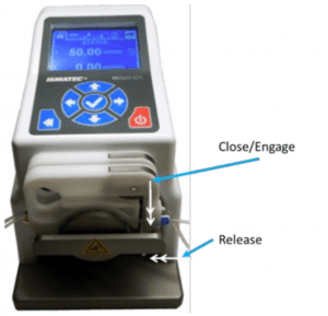
The peristaltic pump has 12 rollers to provide pulse-free operation. Each QCM-I sensor channel is connected to a separate pump channel. These can either be linked so that they always operate together or with an ICC pump can also be controlled independently to allow for different flow rates on different channels.
For linked channels, the flow can be stopped on one channel while the other channel is running by turning the on/off valve off and releasing the tubing clamp on the pump.
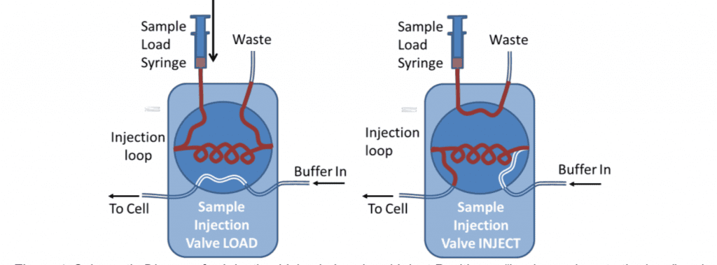
Fixed Volume Sample Injection (6-Port valve)
Samples can be very reproducibly injected with an HPLC type 6-port sample injection valve. This can be used to pass a controlled volume of sample over the sensor (variable upto the total volume of the loop).
For analytical measurements the loop is usually loaded with double its volume of sample and only half of the loop is injected. This is because the buffer pushing the sample through the loop mixes with it at the back of the sample. For these reasons, the loop size should also be at least four times larger than the combined flow-cell and valve-to-cell tubing volume. This can be measured by determining the time for an injected air sample to emerge from the cell using a known pump flow rate. 500l is the minimum loop size typically used. For small volume injections the loop can be only partially filled.
One potential disadvantage of using the loop is that the difference in tubing length, when the valve is switched, can cause changes in the back pressure. This is more likely to be the case at high flow rates or for viscous samples. Depending on the valve model, the internal bore of the valve may also have an effect.
The extended length of tubing can also provide surface area for the adsorption of material from the sample. This means the loop should be thoroughly rinsed between different samples and may be a source of contamination in certain circumstances.
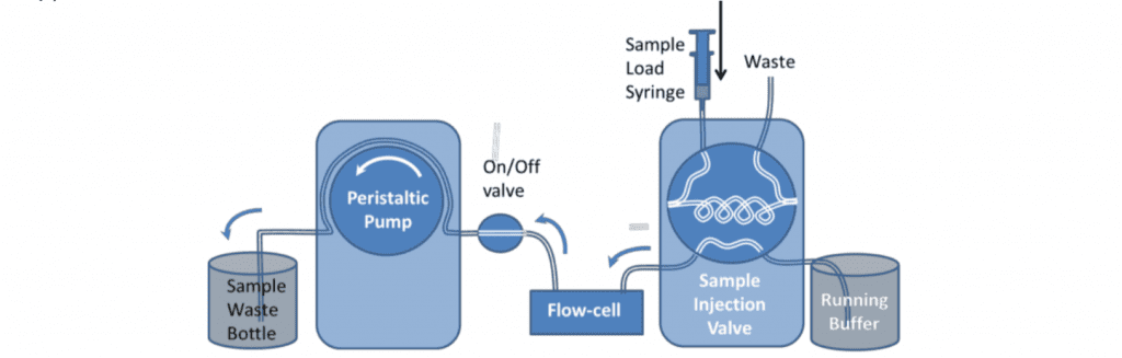
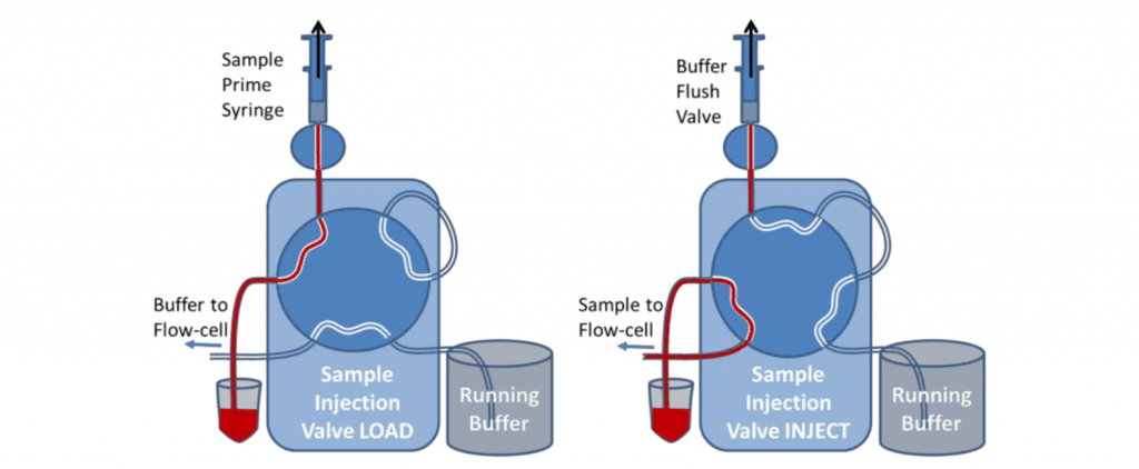
Automated Injection from Sample Vial (6-Port valve)
An alternative arrangement for the 6-port valve allows the automated injection of a sample taken from a sample vial, with continuous flow and without the use of a loop. The advantages of this arrangement are:
- No pressure effect on the flow path after switching,
- Reduced length of tubing to adsorb or desorb sample.
- No dilution of the sample towards the end of the injection, as would be the case if the whole loop was injected
- No limit to the size of sample injected. However the user must ensure that there is enough sample in the sample vial for the length of the injection, otherwise air will be injected to the flow-cell.
The valve is primed with the sample using the priming syringe before the injection. This is similar to loading the sample onto the injection loop. When the valve is switched to Inject, the sample in the vial is sucked by the pump directly to the flow cell. During the initial setup, the valve can be switched to inject and buffer drawn through the valve to eliminate all bubbles and flush the valve fully.
After the sample has been injected, the Sample Load syringe should be used to suck water or buffer through the valve to rinse the tubing before another sample is introduced. For small sample volumes, air should be sucked through the sample load/prime tubing before the sample to prevent the sample from being diluted. Very small sample volumes can be injected and recovered by leaving the valve in the inject position and allowing air to follow the back of the sample. The flow can then be stopped before the air enters the flow-cell and reversed to return the sample to the sample vial. It will be diluted however.
Two-Channel Automated Injection from Sample Vial (10-Port valve)
For a two channel system, a similar setup can be used as shown below using a 10-port valve. The valve switches both channels at the same time, so both channels will undergo the same process.
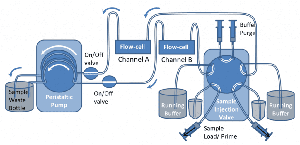
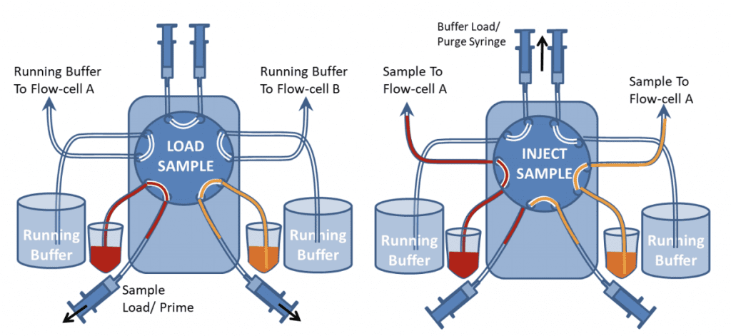
Figure 9 shows the valve in Load and Inject positions. In “Load” position the samples can be loaded onto the valve with the Sample load/prime syringes. The top buffer load/prime syringes should also be used to push buffer through the top part of the valve to ensure air bubbles are excluded from the valve. Different samples can be loaded and injected onto the two channels. If one channel needs a continuous flow of just buffer, both sample inlet and buffer inlet tubes can be placed in the buffer container. However both buffer and sample lines still need to be primed before the injection.
During the initial setup, the buffer purge syringes can be used to fill all the valve with buffer, so that the valve has been completely rinsed and all bubbles are removed.
After samples have been injected, the Sample Load syringes should be used to suck water or buffer through the valve to rinse the tubing before another sample is introduced. If there is only a limited quantity of sample, air should be sucked through before the sample is loaded to prevent it from being diluted by the buffer at the sample/buffer interface in the tubing.
Very small sample volumes can be injected and recovered by leaving the valve in the inject position and allowing air to follow the back of the sample. The flow can then be stopped before the air enters the flow-cell and reversed to return the sample to the sample vial. The sample will be diluted however.
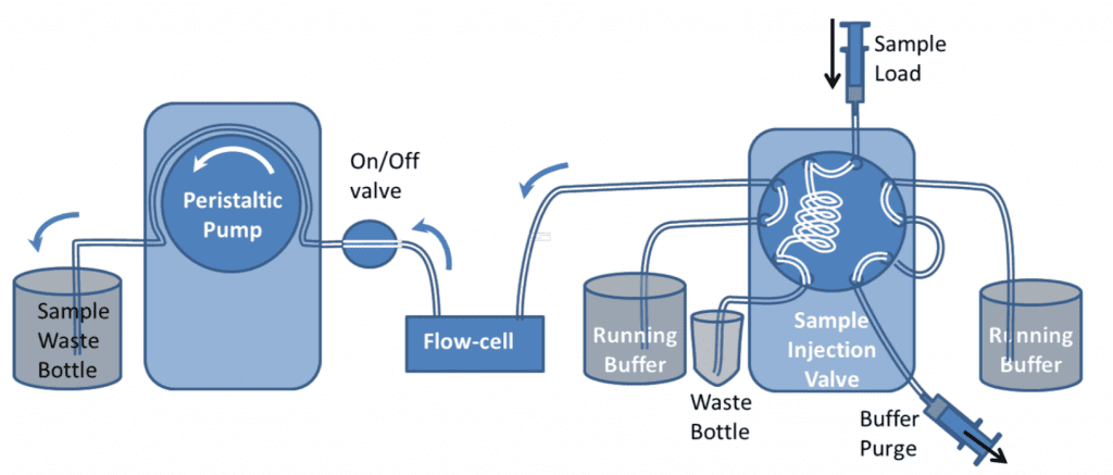
Fixed Volume Sample Injection with a 10-Port Valve
The 10-port valve can be configured to run with an injection loop on a single channel. This is shown in figure 10. The fluidic considerations are the same as with the 6-port valve. The only difference is that the redundant 4 ports can be connected as shown to allow the entire valve to be flushed with buffer.
Technical Note: Dr M. J. Swann 4/2019