Quartz Crystal Microbalance with Impedance Analysis (QCM-I) and Dissipation Monitoring (QCM-D)
The Quartz Crystal Microbalance is a well-established and sensitive technique used to measure the interactions of molecules, polymers and biological assemblies with a sensor surface, in air or liquid, label-free and in real time. It is based on the change in resonant frequency of a quartz crystal sensor when it is covered with a thin film or liquid.
In QCM-I, the impedance of the quartz crystal sensor is measured using a network analyzer to accurately determine the frequency and bandwidth of the crystal resonance. This is done over multiple frequency ranges to measure the fundamental and overtone resonances.
The frequency change is used to determine the hydrated mass coupled to the sensor surface, with sensitivity in the ng/cm2 range and thicknesses of nm to µm. The resonant bandwidth is directly related to the energy dissipation at the interface (QCM-D) and gives information about the viscoelastic properties and structure of the adsorbed layer or viscosity of the liquid.
Quartz Crystal Sensors
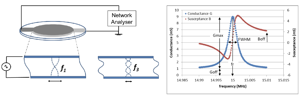
Quartz crystal sensors are thin discs of quartz with electrodes deposited on each side. Because quartz is piezoelectric, when a voltage is applied between the two electrodes a shear displacement is caused in the crystal. If the voltage is alternated, a resonant oscillation can be stimulated in the crystal when the wavelength of the shear displacement in the quartz corresponds to twice the thickness of the sensor. This means that a standing wave can be setup in the quartz with the top electrode moving in the opposite direction to the bottom electrode as shown in figure 1. The frequency at which this happens is the resonant frequency of the crystal. As material is added on top of the sensor, the wave propagates into this layer and the resonant frequency changes. This is the basis of the measurement.
Resonance can also be stimulated at higher frequencies, which correspond to the odd-numbered overtones or harmonics. So a 5 MHz crystal also has overtones at 15 MHz, 25 MHz, 35 MHz etc. As the speed of the acoustic wave in quartz is essentially fixed, the surface displacement is reduced for each successive overtone. This means that different overtones can provide different information about the film on the sensor surface.
Impedance Measurement
The QCM-I uses a network analyzer to measure the complex impedance of the sensor over a range of frequencies around each resonance selected. The software then fits these curves to accurately determine the frequency of the conductance maximum (the resonance frequency, f r ) and the bandwidth of the peak (Full Width at Half Maximum, FWHM), both of which can change in response to changes at the sensor surface. The FWHM can be related to the dissipation (D, determined by QCM-D using the “ring-down” technique) and is inversely proportional to the Quality factor (Q) of the crystal:
FWHM / f = D = 1/Q (1)
Thin Rigid Layer Mass Change – Sauerbrey Film
If a thin rigid layer is added to the surface of one of the electrodes, the acoustic wave extends through this layer and the increased mass causes the resonant frequency to drop. Δf/n is the same for the fundamental frequency and the overtones, but the bandwidth remains the same.
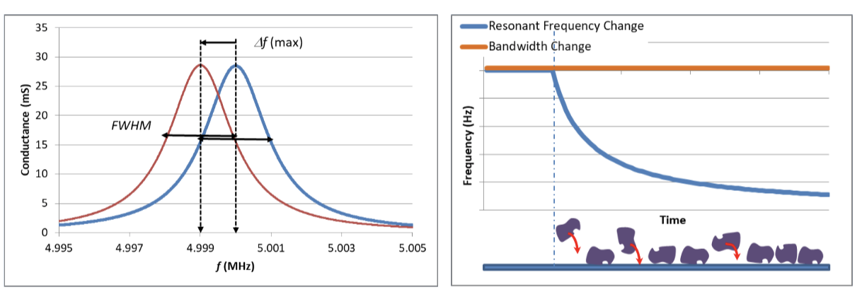
The reduction in the frequency can be related to the change in areal mass (Δm/A) on the surface of one side of the crystal by the Sauerbrey equation:
Δfn = -2n.f12.(Δm/A)/(ρqμq)½ (Hz) (2)
Δm/A = Δfn .(ρqμq)½ / (-2n.f12) (ng/cm2) (3)
Where Δfn is the change in resonant frequency of the nth overtone of a crystal of fundamental frequency f1, Δm is the change in mass (g), A is the area (cm2), ρq is the density of quartz (2.648 g/cm3) and μq is the Shear Modulus of quartz (2.947×10¹¹ gcm-1s-2).
For a crystal with fundamental frequency of 5 MHz, this gives a mass sensitivity [Δm/(Δf.A)] of -17.7 ngcm-2/Hz, or a frequency sensitivity of 56.5 Hz/μgcm-2. The areal mass data from the Sauerbrey equation can also be expressed as a (Sauerbrey) thickness (ds) by using an estimated density for the layer ρ, which is often taken as 1 gcm-3.
ds = (Δm/A) / (ρ.100) (nm) (4)
So a -10 Hz change corresponds to 177 ngcm-2 or a film of Sauerbrey thickness 1.7nm.
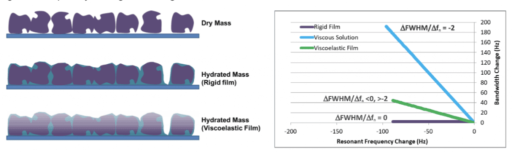
The mass change measured by QCM represents all the mass coupled to the surface of the sensor, including e.g. solvent and salt entrapped within or around a layer of material physisorbed from solution. In this case the mass corresponds to a „hydrated” mass for the layer and is larger than the „dry mass” of the physisorbed material alone.
Changes in Solution Viscosity
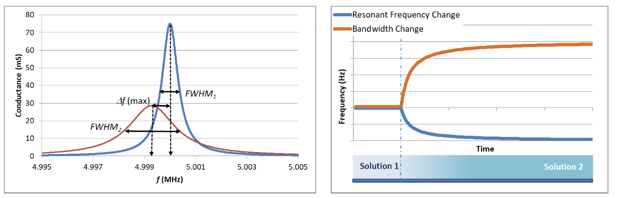
If a bare crystal is immersed in a viscous liquid, or if a viscoelastic film is deposited on the sensor surface from solution, then as well as a reduction in the frequency, the FWHM will increase. The QCM-I signal Frequency and FWHM response to the viscosity and density of Newtonian solution (s) is given by:
Δfn = -n1/2 f13/2 (νsρs )1/2 / (πρqμq)1/2 (Hz) (5)
ΔFWHM = 2 n1/2f13/2 (νsρs )1/2 / (πρqμq)1/2 (Hz) (6)
This means that the response measured for a bulk solution change, due to different viscosity or density of the new solution follows the relationship: ΔFWHMn/Δfn= 2. This is shown schematically in figure 3.
Viscoelastic Films
If a viscoelastic layer is deposited on the sensor surface (or a non-Newtonian fluid), then there is a change in both frequency and bandwidth, as shown in Figure 4. For these films the frequency response due to the added mass is reduced as some of the acoustic wave is dissipated within the film, i.e. less of it is rigidly attached. Viscoelastic models, which rely on various assumptions, can be applied for the more detailed analysis of these layers. The effect of loss of rigidity can also be observed as the frequency change, Δfn/n, is smaller for higher overtones. This means that whilst the Sauerbrey thickness no longer corresponds to the full extent of the hydrated film, using the fundamental frequency will give the closest value to the hydrated mass and thickness. For modelling the films however, the fundamental frequency is not generally used as it is also the most affected by edge effects due to the finite size of the electrodes.
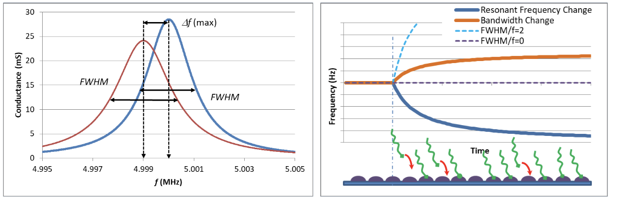
Significant changes of viscoelasticity of a film or solution can also be viewed by plotting Bandwidth against frequency change, as in figure 5.
Technical Note: Dr M. J. Swann
Ref:
1) Sauerbrey, G. Z. Phys. 1955, 155, 206.
2) K. Kanazawa, J. G. Gordon, Anal. Chim. Acta 1985, 175, 99–105.
3) D. Johannsmann, The Quartz Crystal Microbalance in Soft Matter Research:Fundamentals and Modelling, Springer International Publishing, Switzerland, 2015.
4) A.Saftics, G.A.Prósz, B.Türk, B.Peter, S.Kurunczi & R.Horvath, Scientific Reports, 8, 11840, 2018